3.1.3. Coordinate Transformations in 2-D
See also
This video by Peter Corke discusses transformation matrices to apply both translation and rotation.
In the previous section, we looked at the homogeneous transformation matrix applied to a point on a 2-D coordinate frame. Points do not require a specification of orientation; whereas, objects such as robots have orientation as part of the pose description. The homogeneous transformation matrix uses the original coordinate frame to describe both rotation and translation. The transformation matrix is found by multiplying the translation matrix by the rotation matrix.

We use homogeneous transformations as above to describe movement of a robot relative to the world coordinate frame. But in fact, transformations applied to a rigid body that involve rotation always change the orientation in the pose. When defining pose with homogeneous transformation matrices, we are in fact describing a new coordinate frame. When describing a changed of the pose for an end effector at the end of a robot arm, we will usually want to use a transformation where the coordinate frame changes with the rotation. So we want to put the rotation matrix before by the translation matrix in the multiplication.
Consider the pose at the end of a single robotic arm.
Since the rotation changes the orientation of the coordinate frame, the
translation is only along the  axis.
axis.
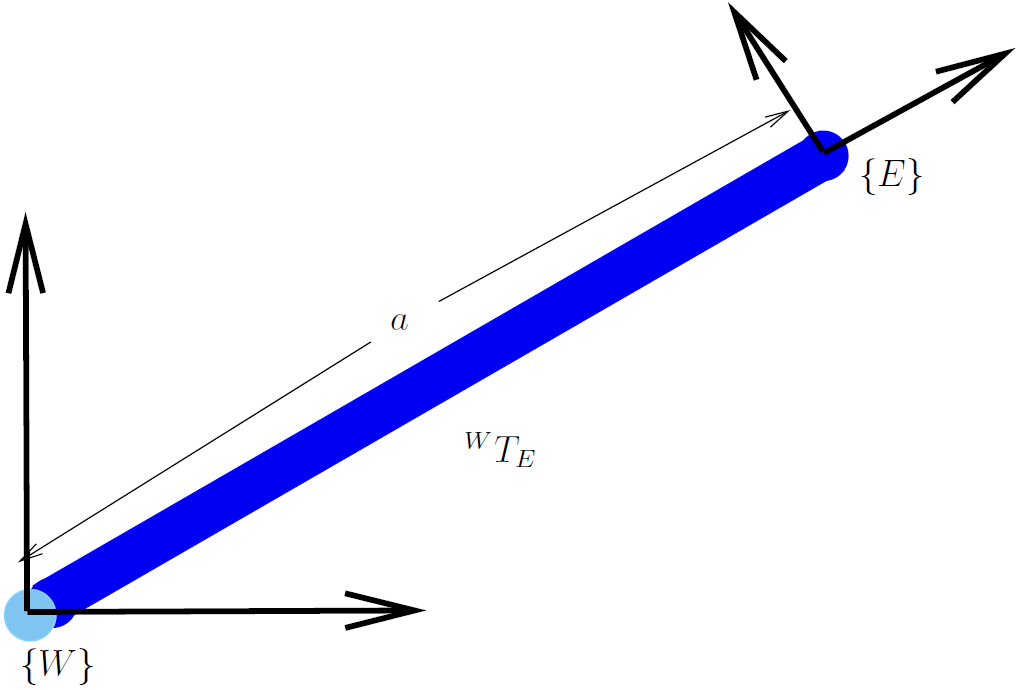
Fig. 3.2 The pose of the end effector is represented by the coordinate frame
 , which is defined relative to the world frame by the
homogeneous coordinate transformation
, which is defined relative to the world frame by the
homogeneous coordinate transformation 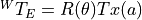 .
.
We read the nomenclature of the coordinate frame transformation
 as the transformation with respect to the world frame,
 , yielding frame . The reference frame is a
prescript to the transformation symbol
, yielding frame . The reference frame is a
prescript to the transformation symbol  , while the label of the
resulting frame is a subscript.
, while the label of the
resulting frame is a subscript.
Note
Some texts, such as Peter Corke’s very fine text Robotics, Vision and
Control use the Greek letter  (xi) for a coordinate
transformation. After considerable debate, I decided to use the simpler
letter . I always found that particular Greek letter difficult
to remember by name and to write correctly. I will use the script symbol
(xi) for a coordinate
transformation. After considerable debate, I decided to use the simpler
letter . I always found that particular Greek letter difficult
to remember by name and to write correctly. I will use the script symbol
 for pose expressed as a vector. I will use brackets
surrounding a letter label, such as
for pose expressed as a vector. I will use brackets
surrounding a letter label, such as  , for labeling of a
coordinate frame.
, for labeling of a
coordinate frame.
The values of the transformation matrix come from the matrix multiplication.
![{}^WT_E = \spalignmat[r]{\cos\theta, -\sin\theta, 0;
\sin\theta, \cos\theta, 0; 0, 0, 1} \,
\spalignmat{1, 0, a; 0, 1, 0; 0, 0, 1} =
\spalignmat[r]{\cos\theta, -\sin\theta, a\,\cos\theta;
\sin\theta, \cos\theta, a\,\sin\theta; 0, 0, 1} \,](../_images/math/0d71873ba167ca333796931d34a727c2ea172c6e.png)
Note: In the translation matrix above, the length of the member
 is only in the row because following the rotation
matrix the coordinate frame was already rotated.
is only in the row because following the rotation
matrix the coordinate frame was already rotated.