5.3.2.2. Using Odometry to Track Robot Movement
Odometry means measuring wheel rotation with the Optical Encoders – like the odometer on your car. Odometry is not always as accurate as one would like, but it is the cornerstone of tracking robot movement.
It is on all robots from inexpensive robots for children to multi-million dollar robots.
Even when Alternatives to Odometry are used, odometry is used as a supplement or back up.
Some Alternatives to Odometry are not easily portable to other locations or may fail to work in certain locations or conditions.
Odometry can be reliable enough to make it quite useful. Just don’t expect it to be perfect. It can especially have problems with drift when the wheels slip on the floor.
5.3.2.2.1. Odometry Calculations
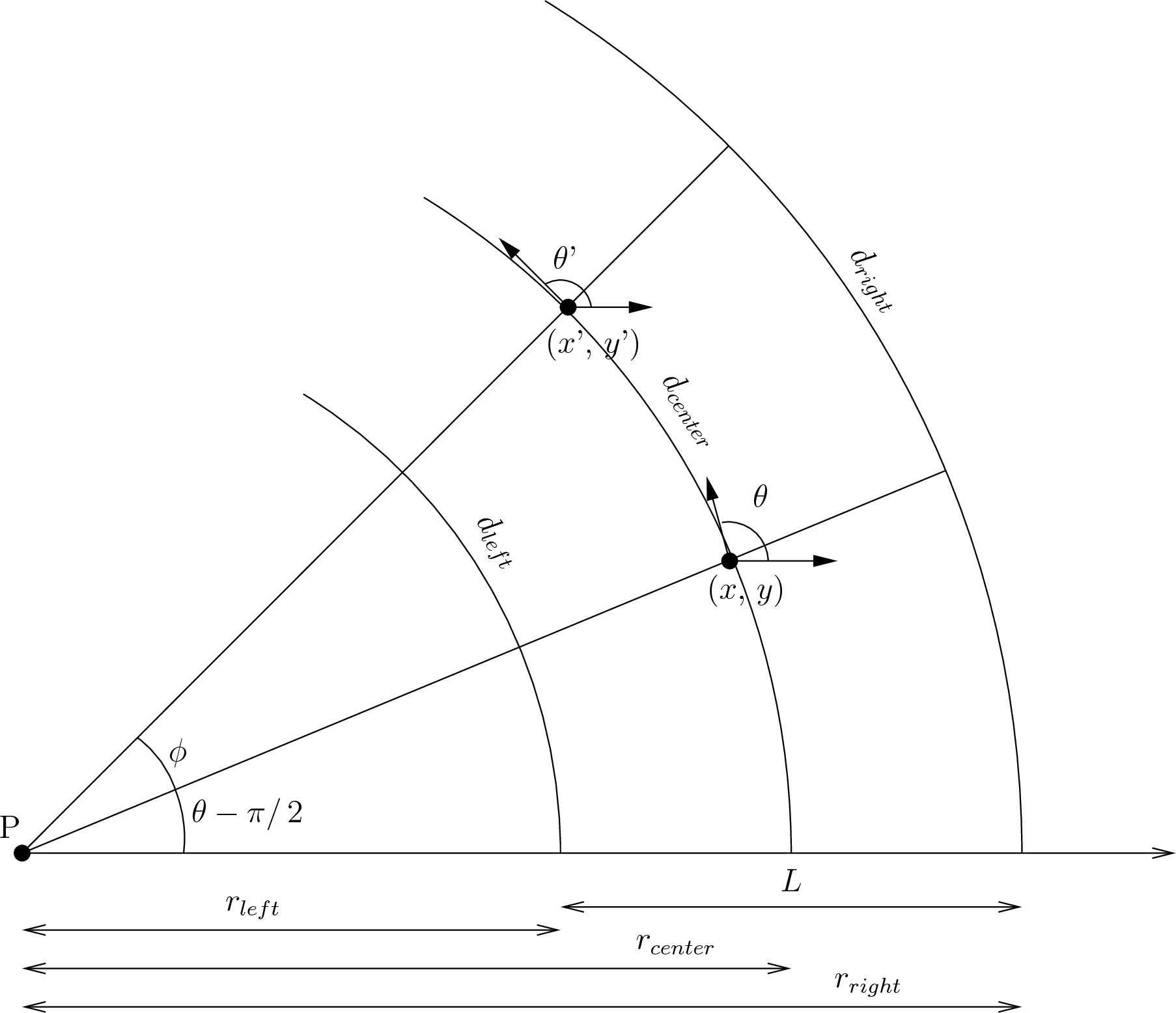
Fig. 5.3 With different wheel velocities, the robot spans an arc.
If the two wheel velocities are different but constant long enough,
the robot will turn in a complete circle around a center point  .
.
5.3.2.2.2. Updating the Robot Position
If in a short time interval,  , the two wheel velocities are
relatively constant, then the robot’s forward velocity,
, the two wheel velocities are
relatively constant, then the robot’s forward velocity,
 , and rotational velocity,
  , and can also be
considered constant and we can update the global position from
, and can also be
considered constant and we can update the global position from
 to
to
 .
.
For the sake of avoiding repetition, the derivation is not shown here, but it is clearly outlined in this short primer by Edwin Olson at MIT.
A Primer on Odometry and Motor Control
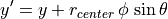
Olson shows that the new position  and
and  are given by:
![x' = x + r_{center}[ -\sin \theta + \sin \phi \cos \theta
+ \sin \theta \cos \phi ]](../../_images/math/1a38dfe946c6a2e09e9262731f217428380b4d39.png)
![y' = y + r_{center}[ \cos \theta - \cos \phi \cos \theta
+ \sin \theta \sin \phi ]](../../_images/math/1fd21d41c1b9980c0b9d93648d478bcb769537e9.png)
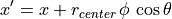
Now, to significantly simplify the equations, an approximation can be made.
If  is small, as is usually the case for small time steps, we
can approximate
is small, as is usually the case for small time steps, we
can approximate  and
and  . Now this
gives us:
. Now this
gives us:
![x' = x + r_{center}[ -\sin \theta + \phi\,\cos \theta + sin \theta ]](../../_images/math/af08e181ae3316f9c20490b4663e602e92fdc222.png)
and
![y' = y + r_{center}[ \cos \theta - \cos \theta + \phi\,\sin \theta ]](../../_images/math/af23154896fd8b88b516c5fba1b33cdafeac70bf.png)
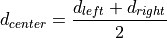
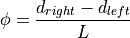
The change in the robot’s direction of orientation, , is the
difference of the distances traveled by the wheels divided by radius of
rotation,  , which is the distance between the wheels.
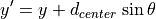
The odometry equations for  are:
are:
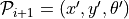
![\mathcal{P}_{i+1} = \left[ \begin{array}{c}
X_i \\ Y_i \\ \theta_i \end{array} \right]
+ \left[ \begin{array}{c}
d_{center}\,\cos \theta_i\\
d_{center}\,\sin \theta_i\\
\phi
\end{array} \right]](../../_images/math/c04dc840f54ab142cae85c751cad50ec43f40c9a.png)
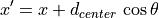
It can also be found in the literature that as a compromise
between the full equation and the simplification of assuming that
 , that the average orientation angle over the time
interval is used to calculate the new position.
, that the average orientation angle over the time
interval is used to calculate the new position.
![\mathcal{P}_{i+1} = \left[ \begin{array}{c}
X_i \\ Y_i \\ \theta_i \end{array} \right]
+ \left[ \begin{array}{c}
d_{center}\,\cos(\theta_i + \phi/\,2) \\
d_{center}\,\sin(\theta_i + \phi/\,2) \\
\phi
\end{array} \right]](../../_images/math/b8280d40289d8ae46381d9395f83c6ae8f732e46.png)
5.3.2.2.3. Alternatives to Odometry
GPS – limited accuracy
Image processing:
One technique that is sometimes used is to use reflective tape to put a square of fixed size on the ceiling. Then using a camera pointed at the ceiling, images of the square can be used to estimate the robot pose.
Triangulation
With three beacons at known locations and a receiver on the robot, it is possible to calculate an exact location of the robot. For example, see this IEEE article about a proposed triangulation algorithm.