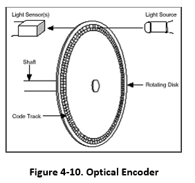
5.3.2.1. Optical Encoders
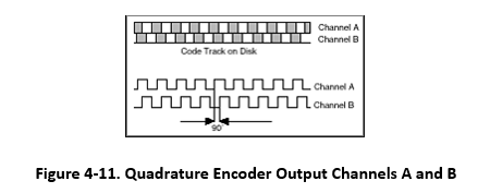
Two lasers shine light beams onto a ring around the axle of each drive wheel. The ring has cuts perpendicular to the rotation. So as the axle and ring turn, the optical receivers detect pulses of light. The two lasers are offset from each other such that the timing of the pulses detected allows the encoder to determine if the wheels are turning forwards or in reverse. The encoder counts the pulses or ticks to determine wheel displacement. The number of cuts in the ring determines the resolution of the encoder (N).
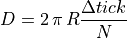
Each time that the encoder is sampled, the difference between the current
tick count and the previous sample is calculated. Then, knowing the number
of ticks per revolution ( ) and the radius of the wheel (
 ),
the distance traveled in the time interval is calculated.
),
the distance traveled in the time interval is calculated.