5.3. Tracking the Robot Pose
5.3.1. Two Frames of Reference
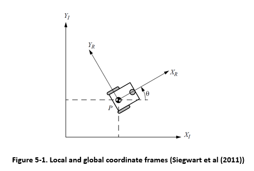
One of the gotchas of robotics is keeping track of which frame of reference
is being used. The global coordinate frame is relative to the robot’s
surrounding. We start robotics experiments with the robot at position (0, 0)
and facing in the direction of the  axis (
 ). The
local coordinate frame is relative to the robot. We use the local
coordinates when measuring the movement or setting the velocity of the wheels.
). The
local coordinate frame is relative to the robot. We use the local
coordinates when measuring the movement or setting the velocity of the wheels.
5.3.2. The Robot’s Global Position
We call the robot’s location and orientation in the global coordinate frame the
position, or pose, of the robot. The robot’s position is represented as a
vector ( ) containing its
  and
and  Cartesian
coordinate pair and its angle of orientation (
Cartesian
coordinate pair and its angle of orientation ( ).
).
![\mathcal{P} = \left[ \begin{array}{c}
x \\ y \\ \theta
\end{array} \right]](../../_images/math/6577d46e6f79956e35873a5ccf4653c0ebd777fa.png)