4.1.1. Forward Kinematics
When we consider each joint of a robotic arm, the observable coordinate
frame of each joint is determined by the previous joint angle and the length
of the previous link. The coordinate frame is relative to the coordinate
frame of the previous joint. We say that the transformation  describes the coordinate frame
  relative to frame
 .
.
Just as we use matrix multiplication to combine rotation and translation into a single transform matrix, so we can also combine multiple transformations. This is called a transformation compound. We just multiply successive transforms starting from the world frame and going to the desired frame. In the multiplication chain, make sure that each subscript frame label matches the reference frame prescript of the next transform.
For example, if a robot has joints labeled A through D and an end effector
labeled E, then  relative to the world frame,
  is
given by the following.

Notice that the subscript frame label of each transform can be thought of as
being canceled by the prescript label of the next transform. Thus to find
 , the first transform has a prescript of
  and the
last transform has a subscript of
  .
.
When defining the pose of an object by means of transformation compounds,
the compound operation is often represented with the special symbol
 .
.

There is also an inverse compound operation denoted with the symbol
 . The inverse compound is used to describe going from an
object back to the pose of the previous coordinate frame. The
 inverse compound is achieved by multiplication by the
inverse of a transformation matrix. This is illustrated in the 3-D example
that follows a simple 2-D example.
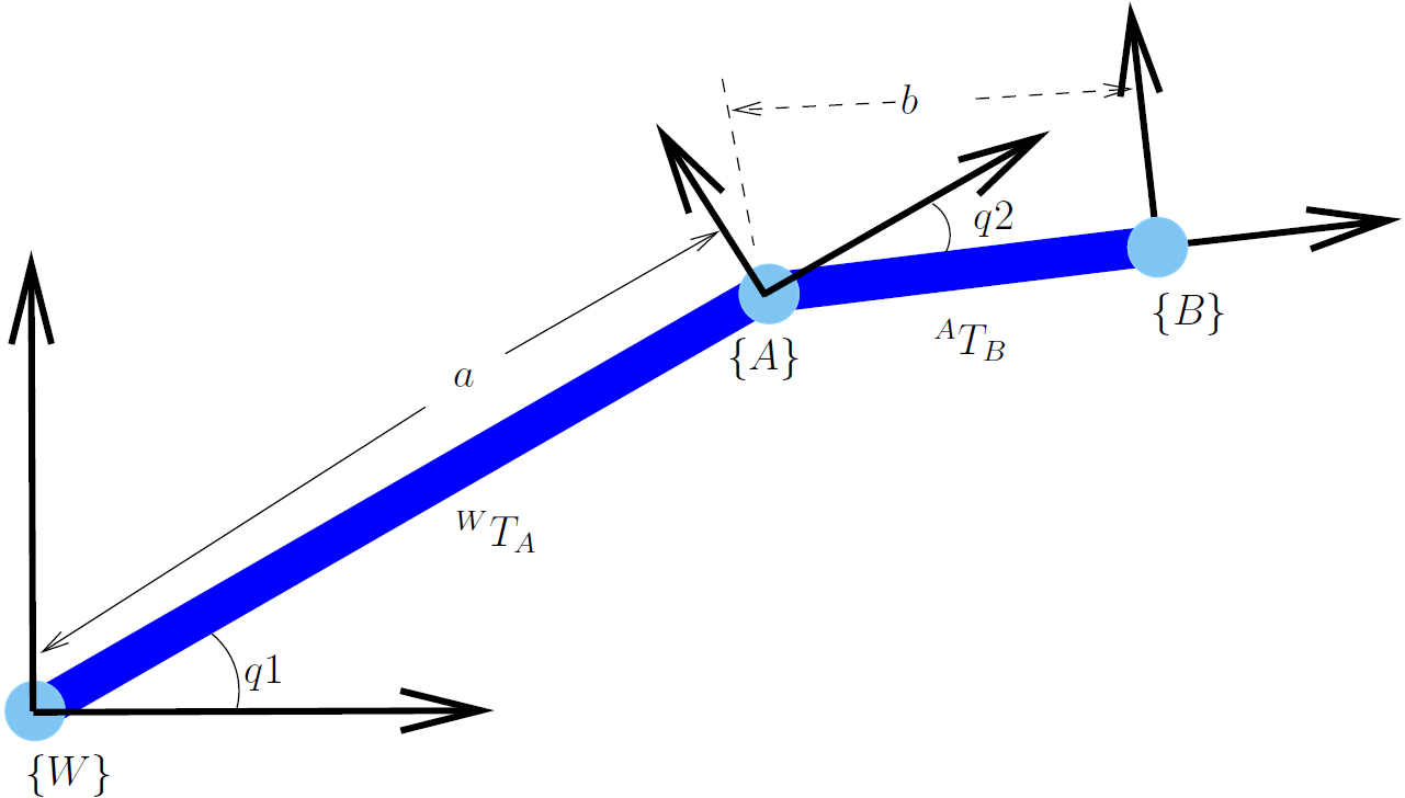
4.1.1.1. Simple 2-D Example

Fig. 4.2  or
or  
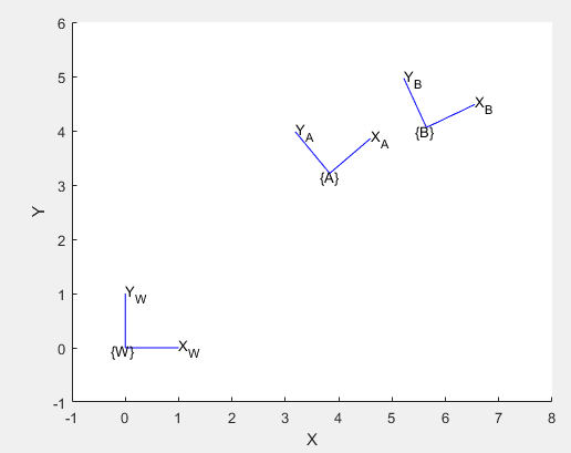
The following shows how MATLAB can compute and display the final coordinate frame.
>> a = 5;
>> b = 2;
>> q1 = pi*40/180;
>> q2 = -pi*15/180;
>> RA = trot2(q1)
RA =
    0.7660   -0.6428         0
    0.6428    0.7660         0
         0         0    1.0000
>> Ta = transl2(a, 0)
Ta =
    1     0     5
    0     1     0
    0     0     1
>> Tb = transl2(b, 0)
Tb =
    1     0     2
    0     1     0
    0     0     1
>> RB = trot2(q2)
RB =
    0.9659    0.2588         0
   -0.2588    0.9659         0
         0         0    1.0000
>> WTA = RA*Ta
WTA =
    0.7660   -0.6428    3.8302
    0.6428    0.7660    3.2139
         0         0    1.0000
>> ATB = RB*Tb
ATB =
    0.9659    0.2588    1.9319
   -0.2588    0.9659   -0.5176
         0         0    1.0000
>> WTB = WTA * ATB
WTB =
    0.9063   -0.4226    5.6428
    0.4226    0.9063    4.0592
         0         0    1.0000

>> figure
>> axis([-1, 8, -1, 6])
>> daspect([1 1 1])
>> hold on
>> trplot2(eye(3), 'frame', 'W')
>> trplot2(WTA, 'frame', 'A')
>> trplot2(WTB, 'frame', 'B')

4.1.1.2. Example of Finding a Relative Vector in 3-D
This forward kinematic example is a little more complex than the previous example. It is in three dimension; and, it also involves an indirect calculation of an unknown vector.
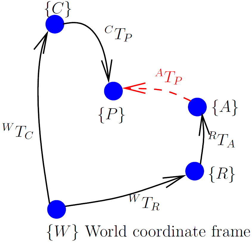
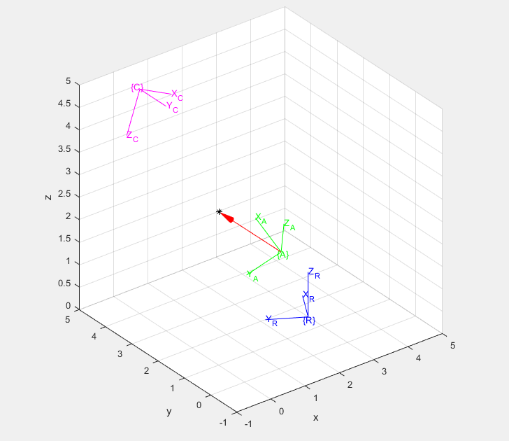
The scene described by the following example script is that of a robot with an arm, and a camera system that finds a vector to an object (point) of interest. Using transformation compounds, it is straight forward to compute the pose of the robot arm in the world frame and also the coordinates of the point in the world frame via the camera. But what is a vector that would go from the robot arm to the point? A directed graph, called a pose graph, can be used to visualize the relationships between the poses of the objects.

Fig. 4.3 The unknown transform is in red.
The transform  can be described using only forward transformation
compounds or as a combination of forward and inverse compounds.

We can solve for  using linear algebra.

To find the unknown transform using an inverse transform, we start at the base of the unknown and work our way with inverse and forward compounds to the tip of the unknown transform.

Or, if we wish to include each relative transform:

Thus, both strategies yield the same result.

Note
The script uses MATLAB’s left divide operator, which is equivalent to
and more efficient than computing the inversere and then multiplying.
In MATLAB, x = A\b; produces the same result with less
computation as x = inv(A)*b;.
%% coordTrans.m
% This script demonstrates transformation of coordinate frames.
%
% A robot is on the ground with a pose.
% The robot has an arm that starts at a set pose relative to the robot.
%
% A camera has a fixed pose.
% The camera finds an object (point) at a specifed pose in the camera's
%   coordinate frame.
%
% What is the vector in the arm's coordinate frame from the arm to the
%   point that the camera found?
%
% Draw a 3D plot showing the coordinante frames and the point. Show the
%   vector from the arm to the point.
%
% This solution uses tool from Peter Corke's Robotics Toolbox
% (http://www.petercorke.com)
%
%% Define given coordinate frames (pose)
% Robot to world frame
wTr = rt2tr(rotz(pi/3), [3; 1.5; 0]);

% arm in robot frame
rTa = rt2tr(rpy2r(0, -pi/6, pi/6), [1; 0.5; 1]);

% Camera in world frame
wTc = rt2tr(rpy2r(pi, -pi/8, 0), [0; 4; 5]);

% Point in camera frame
cP = e2h([2.5; 1; 2]);

%% Convert Frames
wTa = wTr*rTa;  % arm in world frame
wP = wTc*cP;    % point in world frame
aP = wTa\wP;    % point in arm frame => from: wP = wTa * aP
disp('vector from arm to point in arm frame')
disp(h2e(aP));
% check that point in arm frame is same as point in world
wParm = wTa*aP;
disp('Point in World frame via camera')
disp(h2e(wP))
disp('Point in world frame via arm')
disp(h2e(wParm))

%% plot the coordinate frames and point
figure, daspect([1 1 1]), axis([-1, 5, -1, 5, 0, 6])
hold on, grid on
trplot(eye(4), 'frame', 'W', 'color', 'k')
trplot(wTr, 'frame', 'R', 'color', 'b')
trplot(wTa, 'frame', 'A', 'color', 'g')
trplot(wTc, 'frame', 'C', 'color', 'm')
plotp(h2e(wP), '*', 'color', 'k')
[~,armTr] = tr2rt(wTa);
plot_arrow([armTr h2e(wP)], 'r')
hold off

