4. Analysis of Robotic Arms
Robotics arms, also called serial-link manipulators, are used in factories and any industrial setting for tasks such as welding, spray painting, or material handling. They might also be a part of a mobile robot.
A robot arm typically comprises a number of joints. The number of joints in an arm depends on the task that the robot is designed to accomplish. Simple tasks like picking up objects and placing them in containers or at desired locations can be accomplished with only 3 joints. To move to any location on a 2-D plane requires two joints, but a third joint is needed to also control the orientation of the end effector. A robot designed to move to any pose within its reach in three dimensions needs to have 6 joints (6 degrees of freedom). Many industrial robot arms have 6 joints. Some robots need to move within a constrained workspace, so they may have several more joints than 6. Most joints rotate about a pivot point (axle). This is called a revolute joint. Some robot arms also have prismatic joints, which change their length using a telescopic or sliding mechanism.
As the robot’s joints move, the pose of the end effector (tool at the end of the last link from the robot’s base) changes. To design and program a robot arm to accomplish an objective, we need to understand how the pose changes as the joint angles change.
A critical concept for the discussion of robotic arms is that of coordinate frames. With mobile robots, we consider the world coordinate frame and coordinate frame of the robot. With robotic arms, we need to think about the coordinate frame of each joint in the arm.
Expensive, commercial robots that are commonly used in industry have
internal software that greatly simplifies how robot movement is specified in
programs. It is common with such robots to define what is called a tool
coordinate frame as a coordinate frame for the end effector
relative to the surface of a work piece. Having defined the tool coordinate
frame, the program need only specify how the end effector is to move
relative to the surface of the work piece. When the program tells the robot to
move to  points in the tool coordinate frame, the software
in the robot control computer calculates how to move each joint of the arm.
points in the tool coordinate frame, the software
in the robot control computer calculates how to move each joint of the arm.
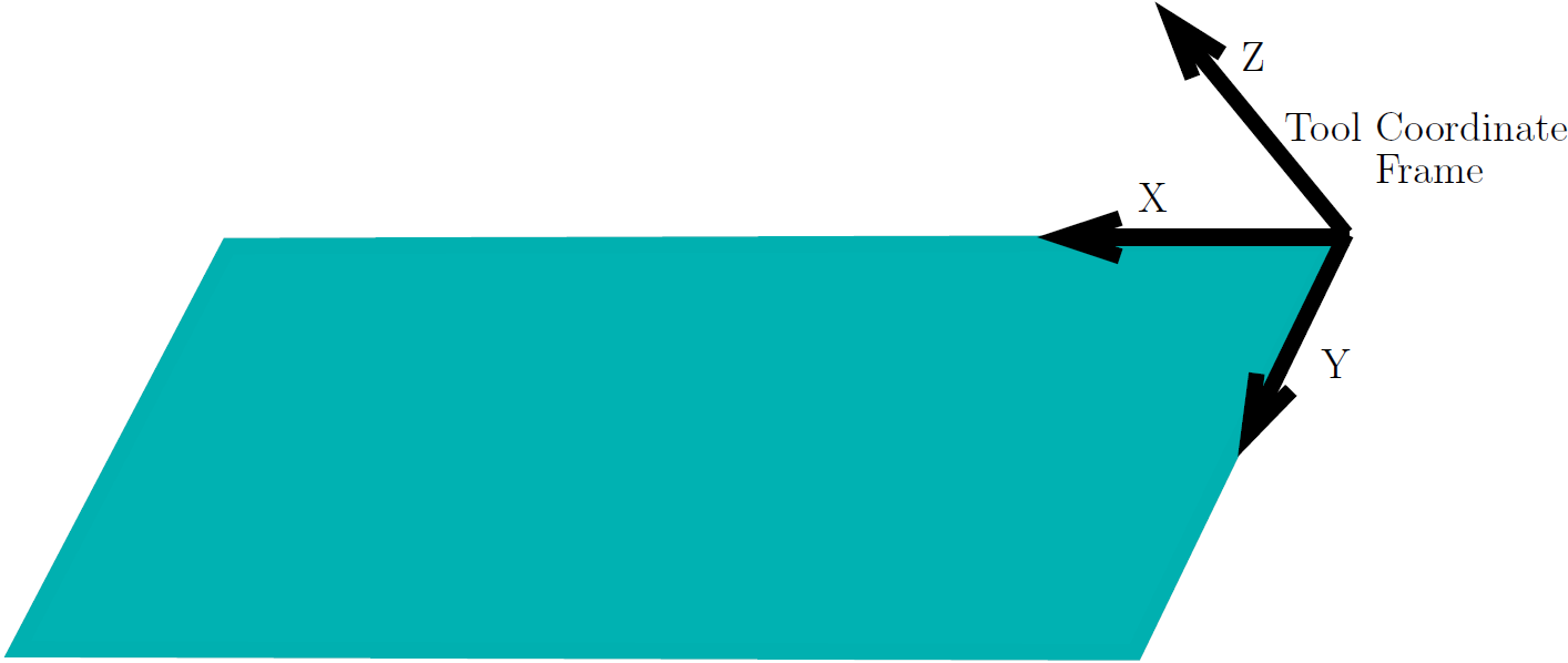
Fig. 4.1 The location and orientation of the tool coordinate frame origin is specified to conveniently describe movement of the end effector relative to the work piece.
We will consider how the joint angles relate to the pose of the end effector. The material covered here relates to what an industrial robot controller software would calculate and what programs for less expensive robots need to incorporate.
If you’d like more information on vectors, matrices, matrix multiplication, and transforming vectors, look at the following Khan Academy videos:
Contents: