3.2.1. Rotations in 3-D
You might naturally think of 3-D rotation as an orientation towards a 3-D vector with a certain roll about that vector. Such a description may be simple to visualize, but it is fairly complex to describe mathematically. The relationship between the resulting 3x3 rotation matrix and the orientation vector and roll angle is defined in terms of the eigenvectors and eigenvalues of the rotation matrix. Page 41 and 42 of [CORKE17] discuss this.
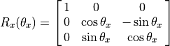
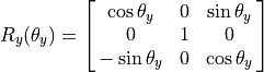
A more common way to define 3-D rotations is by one or more successive rotations about one of the three orthogonal axis of a coordinate frame.
Rotation about the  axis is the same as 2-D rotation previously
discussed (see Rotation of a Point). The rotation matrices can be directly
gleaned from examining the geometry of rotated unit vector coordinate
frames. In each diagram below, the rotation axis comes out from the graph,
perpendicular to the plane formed by the two axes shown.
axis is the same as 2-D rotation previously
discussed (see Rotation of a Point). The rotation matrices can be directly
gleaned from examining the geometry of rotated unit vector coordinate
frames. In each diagram below, the rotation axis comes out from the graph,
perpendicular to the plane formed by the two axes shown.
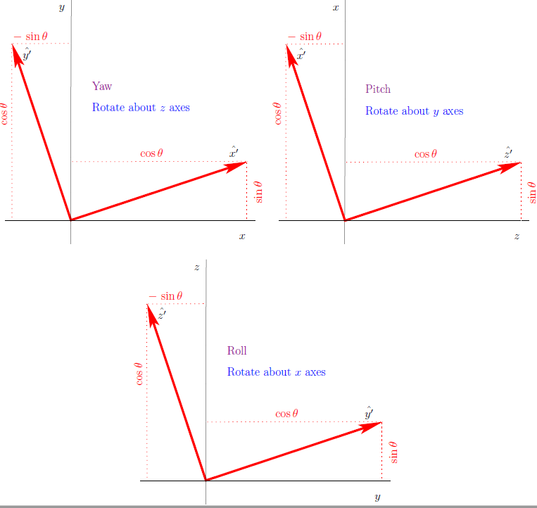
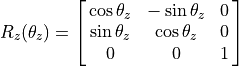
The columns of the rotation matrices define three unit vectors
( ) of the rotated coordinate frame. The
rows represent the multipliers of the original unit vector coordinate frame.
Note that the column representing the rotation axis is unchanged; and thus,
it receives a one at its row and zeros in the other two rows.
) of the rotated coordinate frame. The
rows represent the multipliers of the original unit vector coordinate frame.
Note that the column representing the rotation axis is unchanged; and thus,
it receives a one at its row and zeros in the other two rows.
Note
To find the rotation direction, use the second right hand rule shown on Transformations in 3-D. Point your right thumb in the direction of the axis to be rotated around and curl your fingers. Your finger tips will point in the direction of a positive rotation angle.
3.2.1.1. Rotation Order
Swiss mathematician Leonhard Euler (1707 - 1783) gave us Euler’s rotation theorem.
Like matrix multiplication, rotations are not commutative (order matters). Therefore, it is necessary to specify the order of the rotations. The following MATLAB session illustrates that rotations are not commutative.
>> Rx = rotx(0.1)
Rx =
    1.0000         0         0
         0    0.9950   -0.0998
         0    0.0998    0.9950
>> Ry = roty(0.2)
Ry =
    0.9801         0    0.1987
         0    1.0000         0
   -0.1987         0    0.9801
>> Rz = rotz(0.15)
Rz =
    0.9888   -0.1494         0
    0.1494    0.9888         0
         0         0    1.0000
>> Rx*Ry*Rz
ans =
    0.9691   -0.1465    0.1987
    0.1683    0.9809   -0.0978
   -0.1805    0.1283    0.9752

>> % changing the order changes the net rotation
>> Rz*Ry*Rx
ans =
    0.9691   -0.1291    0.2104
    0.1465    0.9868   -0.0692
   -0.1987    0.0978    0.9752
There are twelve sets of three successive rotations satisfying Euler’s requirement of no two successive rotations being about the same axis (XYX, XZX, YXY, YZY, ZXZ, ZYZ, XYZ, XZY, YZX, YXZ, ZXY, ZYX). All of these sequences can be referred to a Euler angles, but in practice, only two are in common usage.
3.2.1.1.1. Euler Angles
The ZYZ rotation sequence is the implied rotation sequence when they are called Euler Angles. The sequences is often used in the fields of aeronautics and mechanical design.
3.2.1.1.2. Roll, Pitch, Yaw
The XYZ rotation sequence is also in common usage. It is called roll - pitch - yaw, or just RPY. The sequence is intuitive when describing the attitude of moving machines such as ships, aircraft, cars, and robots.
We will describe robot part rotations using the RPY sequence.
The X-axis is considered to be the machine’s forward direction. The Z-axis is usually oriented in the upward direction; however, with aircraft the Z-axis is often in the downward direction.
Rotation about the X-axis is called roll.
Rotation about the Y-axis is called pitch.
Rotation about the Z-axis is called yaw.
3.2.1.1.3. Gimbal Lock
When possible, systems are designed so that a pitch angle of  is impossible. Otherwise, a highly undesirable situation occurs.
For an airplane, a pitch of means that the plane is going
straight up. The coordinate frame for airplanes is oriented with the x-axis
pointing forward and the z-axis pointing down. Thus, if the pitch (rotation
about the y-axis) is , then the plane is vertical pointing up
against gravity. Obviously, the coordinate frame for a rocket is oriented
differently because they are launched vertically.
In the movie Apollo 13, this situation is called gimbal lock, and reaching it would have meant that the craft’s navigation system would become unreliable, which might have made it impossible for the astronauts to return to Earth.
Gimbal lock is fully explained in this interesting YouTube Video by Peter Corke.