5.5.1.4. Wall Following
The Hybrid Avoid Obstacles and Go-to-Goal algorithm alone can not solve The Cul-de-sac Problem. We need a behavior that will cause the robot to move parallel to the obstacle and even move away from the goal if needed to move around a non-convex obstacle.
As with Hybrid Avoid Obstacles and Go-to-Goal, the robot heading ( ) is calculated as
the weighted sum of
) is calculated as
the weighted sum of  to avoid obstacles and a value
called
to avoid obstacles and a value
called  which will be designed to follow the turns of a
wall at a fixed distance
which will be designed to follow the turns of a
wall at a fixed distance  . Since the robot is expected to
follow somewhat near a wall, will be larger than it was
for the Hybrid algorithm, so we will use a larger threshold value to
calculate the weighting variable
. Since the robot is expected to
follow somewhat near a wall, will be larger than it was
for the Hybrid algorithm, so we will use a larger threshold value to
calculate the weighting variable  .
.
(5.6)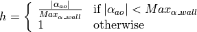

Thus, for  , we have pure
collision avoidance:
, we have pure
collision avoidance:

Note that when the wall ahead of the robot turns in towards the robot, the
term will dominate the equation. When the wall is
straight or turns away from the robot, the value of
becomes critical to the heading angle calculation.
5.5.1.4.1. Perpendicular Vector Wall Follower
This algorithm uses a bit of linear algebra of vectors to find a point to drive to that keeps such that a wall is followed. It requires the robot to have five distance sensors (one in front and two to each side of the robot pointing at about 45 and 90 degrees to the robot).
Let the end points of the first two distance sensors on the side of the
robot towards the wall be points  and
and  in the world
coordinate frame. Given the pose of the robot, we can find a vector from the
robot to point ,
in the world
coordinate frame. Given the pose of the robot, we can find a vector from the
robot to point , ![\bm{A} = p1 - [x\: y]^T](../../_images/math/70de04a4e273b24cc9f63c6e48557784d15710f3.png) . We can also define
a vector between points and ,
. We can also define
a vector between points and ,  .
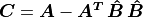
Vector
.
Vector  generally defines the direction that the robot should
travel; but more specifically, we wish to drive towards a point
distance from the closest point along vector
to the robot. The closest point is
generally defines the direction that the robot should
travel; but more specifically, we wish to drive towards a point
distance from the closest point along vector
to the robot. The closest point is  from point
, where
from point
, where  is a scalar value that we need to find and
 is a normalized (unit vector) of . We
will use a vector,
is a normalized (unit vector) of . We
will use a vector,  , from the robot to
to find the target driving point.
, from the robot to
to find the target driving point.


Since vectors and are to be perpendicular,
the dot product between the vectors should have a value of zero.
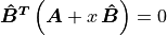
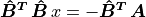
Since is a unit vector,
 . Vectors of dot products may
also be reversed if desired.
. Vectors of dot products may
also be reversed if desired.

Now the vector,  defining the robot driving direction is
given by
defining the robot driving direction is
given by
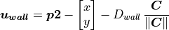

The robot’s current position is subtracted because is in the
global coordinate frame.
As mentioned before, this driving vector should be blended with the vector
for avoiding obstacles.
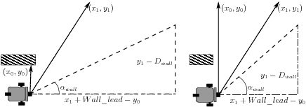
5.5.1.4.2. Virtual Triangle Wall Follower
This algorithm is one that I developed in 2015. It is based on trigonometry
functions to give a smooth turning behavior. The algorithm forms a model of
a right triangle where sonar measurements determine the lengths of the sides
opposite and adjacent to the angle .
The calculation uses the  coordinates from the first two sonar
measurements on the side of the wall.
coordinates from the first two sonar
measurements on the side of the wall.
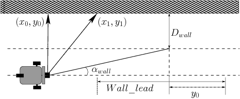
Fig. 5.5 Right Triangle Model for Wall Following
Use the atan2 function to calculate :

The length of the second sonar measurement is an indicator of the near
future path provided by the wall. Thus the right triangle model begins with
 on the adjacent and opposite sides of the triangle. The
vector to always spans the same angle, but the length of
the measurement relates to the distance from the wall and turns in the wall
ahead.
on the adjacent and opposite sides of the triangle. The
vector to always spans the same angle, but the length of
the measurement relates to the distance from the wall and turns in the wall
ahead.
The value of , which is a tunable constant, indicates how
far from the wall we want to be. Thus  is the length
of the opposite side of the triangle. If
is the length
of the opposite side of the triangle. If  , then
the robot is following the wall as desired.
, then
the robot is following the wall as desired.
The adjacent side length is calculated from three variables.
Like
 ,
,  has valuable information about the contour
of the wall. It will be shorter if the wall turns in towards the robot and
longer if it turns away. When the robot nears the end of a wall that turns
away from the robot, both and will become much
larger.
has valuable information about the contour
of the wall. It will be shorter if the wall turns in towards the robot and
longer if it turns away. When the robot nears the end of a wall that turns
away from the robot, both and will become much
larger.The second variable,
 is a tunable constant to
effectively adjust the gain of the controller. The initial value was set
at 2 meters. It should be increased if the robot is turning too
aggressively and reduced if the turning is too sluggish.
is a tunable constant to
effectively adjust the gain of the controller. The initial value was set
at 2 meters. It should be increased if the robot is turning too
aggressively and reduced if the turning is too sluggish.The minimum value of
can be calculated by considering
the maximum value that we want ,  seems
reasonable. Taking the maximum values for the two sonar measurements and
their angles, when
seems
reasonable. Taking the maximum values for the two sonar measurements and
their angles, when  ,
,
 , so our value of 2.0 seems reasonable.
The value of
 tells us how far the robot currently is from the
wall. When the robot reaches the end a point where the wall turns away
from the robot, will suddenly become larger. Since this value
is subtracted from length of the adjacent side of the model right
triangle, this increased size of will cause the robot to turn.
Thus, when the wall turns away from the robot, can be
considered a gating factor to keep the robot from turning until robot goes
past the end of the wall.
Correspondingly, when the robot is close to the wall, the small value of
will cause the robot to turn away from the wall.
tells us how far the robot currently is from the
wall. When the robot reaches the end a point where the wall turns away
from the robot, will suddenly become larger. Since this value
is subtracted from length of the adjacent side of the model right
triangle, this increased size of will cause the robot to turn.
Thus, when the wall turns away from the robot, can be
considered a gating factor to keep the robot from turning until robot goes
past the end of the wall.
Correspondingly, when the robot is close to the wall, the small value of
will cause the robot to turn away from the wall.