2.4. The Nature of Motors
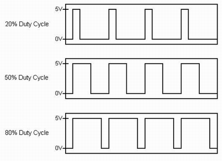
Active electronics are needed to translate digital motor levels from the robot’s computer to signals capable of turning the motors. Robot’s use DC motors that can run forward or reverse depending on the polarity of the input voltage. To accomplish this, the digital control signal from the robot is often in the form of a PWM waveform. When the electronics perform an analog integration of the PWM waveform, the resulting analog voltage will correlate to the duty cycle of the PWM signal. This voltage can then be shifted and scaled to produce positive and negative voltages at the desired levels.
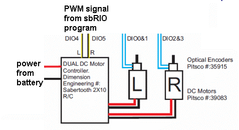
The PWM signal can generate the desired the voltage levels for the motors, but the current needed to drive the motors must come from the battery. The voltage regulator combines power from the battery with the PWM control signals to produce analog signals with the desired voltage and sufficient current to power the motors.
2.4.1. Gear Boxes
The DC motors used with mobile robots can run quite fast, but do not have enough torque to move the robot. Thus it is necessary to use a transmission or gear box between the motors and the wheels. Some motors come with a gear box attached to them and sometime they are added externally. The gear reduction for these motors is typically in the range of 30:1 to 100:1. For applications requiring more torque, gear ratio of 250:1 or even higher might be used.
2.4.2. Servo Motors
Servo motors accept a command of where to turn to in radians
( to
to  ).
They accept a digital signal and require DC power.
One issue with servo motors is that some delay in the program is usually
needed to give the motor time to move to the desired position.
).
They accept a digital signal and require DC power.
One issue with servo motors is that some delay in the program is usually
needed to give the motor time to move to the desired position.
2.4.3. Speed Control
The speed of the motors corresponds to the voltage levels supplied, current momentum and external forces that load the motors. If we want to program the wheels to turn at a certain speed, then we need a controller to use the optical encoder to monitor the current speed and adjust the voltage levels up or down accordingly. See The PID Controller.
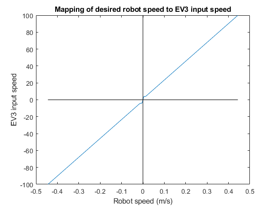
Some robotics platforms have built-in PID controller to set the speed of the motors. The National Instruments DaNI robots use a PID controller where the input is in units of radians per second. The Lego EV3 controllers also have PID motor controllers, but the input uses a scale of -100 to 100 without reference to the resulting motor speed.
In the case of the Lego EV3 controllers, it is tempting to add a PID controller to adjust the inputs to make sure that the desired speeds are achieved. Unfortunately, the frequent speed changes from the PID cause the internal controller to reset each time and actually delay reaching the desired steady state. Another approach is to map the observed robot speed (found from an experiment) to the corresponding EV3 speed input. In doing so, we have to pay special attention to the threshold level where the wheels do not turn when the input speed is less than the threshold. In the experiment, the line equation for the mapping was found using least square regression. See notes on Least Square Regression.