14.10. A Change of Coordinate Frames
Note
This project is more of a class activity than a traditional homework assignment.
Robotic programming environment often provide multiple coordinate frames as a convenience to the programmer. They provide a world coordinate frame where the (X, Y, Z) positions are relative to the base of the robot. A work-piece coordinate frame can also be configured, which allows a coordinate frame to be established with points relative the piece being worked on. In this problem, we will consider a sheet of metal at a 30 degree angle along the x-axis (rotated about the y-axis). Another rectangular piece of metal is to be welded perpendicular to the work-piece at a fixed location and then another piece welded to its top. Our robot needs to make two weld lines. To help the robot weld straight lines, we need to find a set of points along the weld lines that are 1/8 inch apart. The location of the weld lines in the work-piece coordinate frame are shown in the code below.
We need to transform the points from work-piece coordinates to world coordinates. To do this, we add the base of the work-piece coordinate frame to a transformation of the points. A set of points parallel to the work-piece along the x-axis (fixed Z coordinate) are at a 30 degree angle in the world coordinate frame. We can find the transformed points by setting the work-piece coordinates in a \(3{\times}1\) column vector and multiplying by a \(3{\times}3\) transform matrix. The diagram below shows a side view of the work-piece and a line perpendicular to the work-piece. Red lines make right triangles that will help us determine the transformation matrix based on the trigonometry of the right triangles.
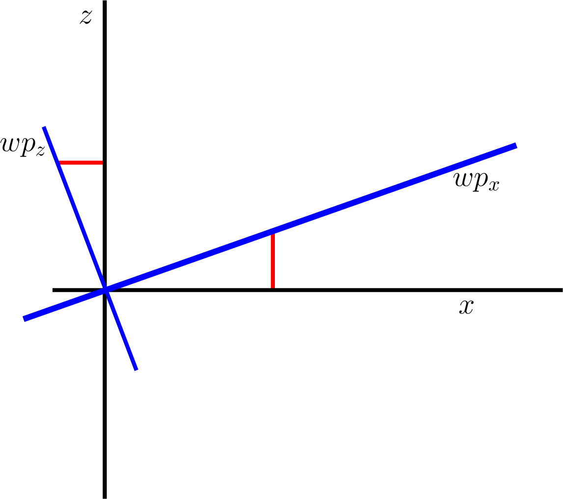
Fig. 14.3 Side view of the work-piece at 30 degree angle and perpendicular line
If the transformation matrix is correct, MATLAB will draw the work-piece surface as a plane and lines where the welds are to be made.

Fig. 14.4 Weld lines on and 10 inches above a work-piece
Most all of the code is provided for you. Just fill in the values of the transformation matrix. Submit your program and the plot, saved as a PNG file on Canvas.
%% Change_coords.m
% Tim Bower, 5/8/2020
%    Demonstration of changing the coordinate frame between a robotic
% work-piece coordinate frame and the world coordinate frame.
% A work-piece surface is defined as starting at [10; -20; 30] in
% world coordinate frame and tilting up from there at 30 degrees in x-axis.
%    The robot needs to make two 30-inch welds from points
% [5; 30] to [23; 6] on the work-piece surface and 10 inches above and
% parallel to the work-piece.  To make straight line welds, the robot needs
% a set of points 1/8 apart in the world coordinate frame.

% Parallel 30 inch lines 1/8 inch apart in work-piece coordinates, one on
% the work-piece surface and one 10 inches above.
line1_wp = linepoints([5; 30; 0], [23; 6; 0], 1/8);
line2_wp = linepoints([5; 30; 10], [23; 6; 10], 1/8);
points = size(line1_wp, 2);

% pre-allocate storage
line1_rw = zeros(3, points);
line2_rw = zeros(3, points);

% Map points of the two weld lines to the robot's
% world coordinate frame.
Base_wp = [10; -20; 30];  % world coordinates of wp base
c30 = cosd(30);
s30 = sind(30);

%% YOU DO THIS: Fill in the 3x3 transformation matrix
% Consider how the world coordinates change with these three
% work-piece coordinates: [1 0 0]', [0 1 0]', [0 0 1]'

T = [ ]; % Orthogonal transform

%%
for p = 1:points
    line1_rw(:,p) = Base_wp + T*line1_wp(:,p);
    line2_rw(:,p) = Base_wp + T*line2_wp(:,p);
end

% points for plotting the work-piece surface
[X, Y] = meshgrid(linspace(0, 40*cosd(30), 20), linspace(-20, 50, 20));
Z = 30*ones(20) + X*sind(30);
X = 10*ones(20) + X;

% points for plotting the two weld lines
x1 = line1_rw(1,:);
y1 = line1_rw(2,:);
z1 = line1_rw(3,:);
x2 = line2_rw(1,:);
y2 = line2_rw(2,:);
z2 = line2_rw(3,:);

% Make a surface plot of the work-piece and plot the two weld lines.
figure
hold on
surf(X, Y, Z, 'FaceAlpha',0.5)
plot3(x1, y1, z1, x2, y2, z2, 'LineWidth', 3)
hold off
grid on
xlabel('X');
ylabel('Y');
zlabel('Z');

function wp = linepoints(start, finish, space)
% LINEPOINTS -- Generate a set of points of a line between start and finish
% points at a specified spacing.
    v = finish - start;
    len = norm(v);
    p = 0:space:len;
    step = v/len;
    wp = start + p.*step;
end